


This article describes the Wyoming Division HO scale
layout built in a 3,750 square foot building with a
separate 1,080 square foot shop in Cornville, AZ 17
miles from Sedona.
The Wyoming Division models the 485 miles of Union
Pacific from Cheyenne to Ogden in HO. It is built on a
two level standalone mushroom steel framework bench
and has 859 feet of double main line track with a 1957
era, and including the main tracks through staging and
the staging helix the length is 1,006 feet. The layout
has over 5,300 feet of track. The minimum Main line
track radius is 36 inches using Atlas Code 83 Flex
Track. Peco and Shinohara turnouts and NCE radio
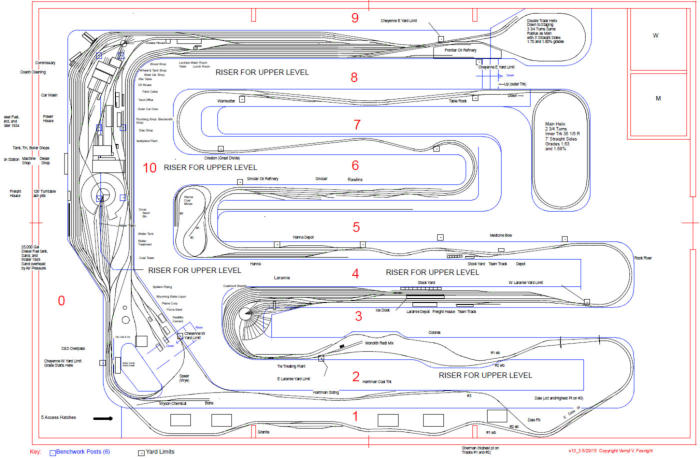
control DCC are used. The first three Figures show the
upper and lower deck track plans.
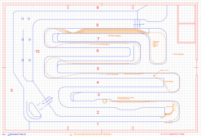
Figure 1. Upper level track plan
There were 10 tunnels on this section of the Union Pacific, and all have been included them by scaling them in length by using
an empirical linear equation as a scaling “factor” that makes the longer real tunnels modeled proportionally longer than the
model real ones. The model grades were made proportional to the prototype average grades over selected lengths of track.
Those lengths and grades were taken from a set of 1961 UP Profile Charts. Various locations were picked between which there
is a generally uniform up or down slope to the grade, and then the average grade between those two points was calculated.
The prototype has few inundations generally, so this is reasonable to do, and these small changes have little effect on
the average grade. Then the model average grade was set at 1.6 times that of the prototype average over those lengths.
The model grade runs from Cheyenne with the
reference elevation of zero to +10.66 inches at
Sherman. The model grade is 2.48% which is 1.6x the
prototype 1.55%. This 2.48% requires helpers to take
25 to 30 car trains up the Hill. The model grade from
Ogden up Weber Canyon and Echo Canyon (the
Wasatch Mountains) is not so steep (about 1.8% model,
1.14% prototype), again in a ratio of 1.6. Following
prototype practice, helpers are used from Ogden to
Green River, Wyoming as well as up Sherman Hill. UP
often cut off the helpers at Wasatch, Utah, but on the
model the helpers go on to Green River to use the
turntable there to turn them back to Ogden.
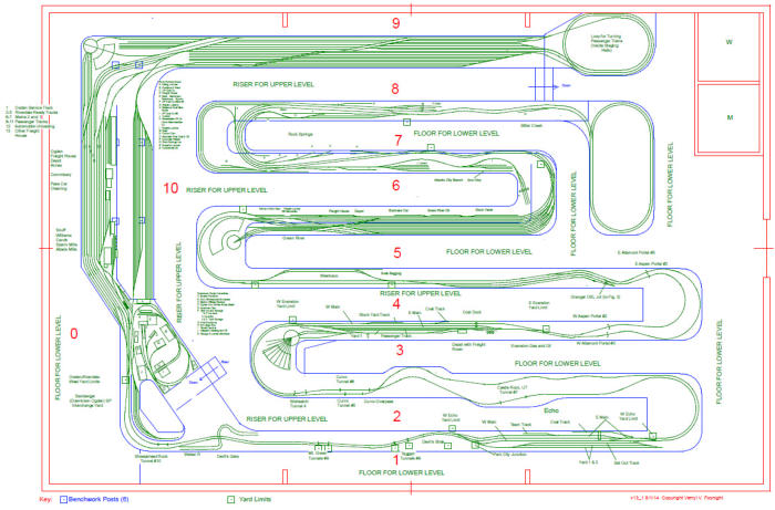
Figure 2. Lower level track plan
Figure 3. Hidden Track or third level track plan
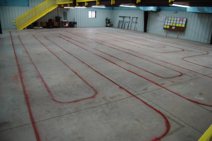
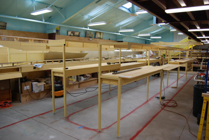
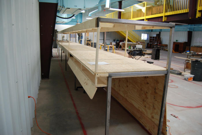
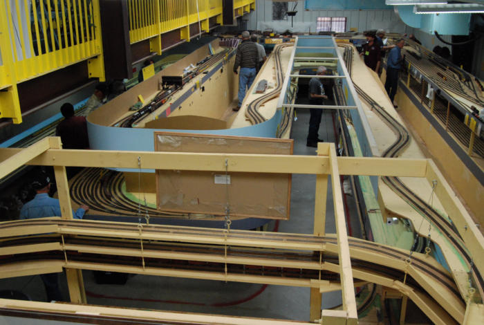
The next photo shows the interior of the building that was built
specifically for the Wyoming Division. The red lines outline the
benches of varying widths and 41 inch wide aisles. The benches
range from 24 to 34 inches wide, but Cheyenne (upper level) and
Ogden (lower level) are a whopping 84 inches wide. This 84”
width for this one bench was felt necessary to model the entire
Cheyenne yard from Tower A through the end of the freight yard.
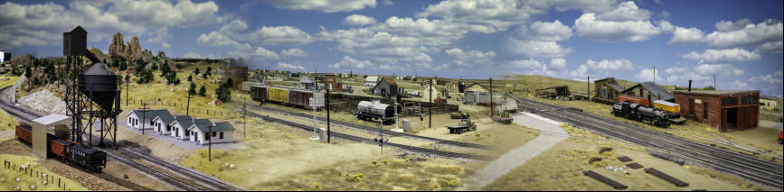
Cheyenne in the ‘50’s had one of the largest steam facilities in the
world, and for historical accuracy it was necessary to model it all.
A picture of that model is shown in Figure 5. Part of Ogden can
be seen on the lower level.
Figure 4. Empty Building with benches laid out on floor
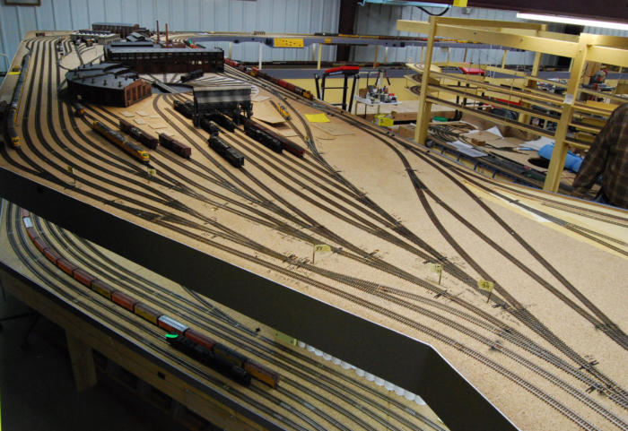
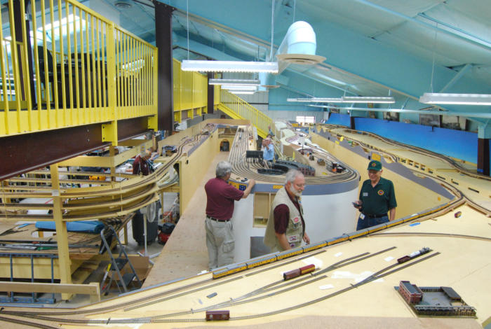
Figure 5. Cheyenne Steam Yard from the west on upper level. Ogden is on the lower level.
HOW TO OPERATE SUCH A VERY WIDE BENCH
The very wide bench shown in Figure 5 is impossible to reach across to throw turnouts with ground throws, so electric switch
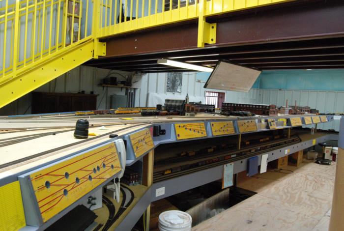
machines were the required. Lenny Wyatt made the panels shown in Figure 6 with recessed electrical switches to control
Tortoise switch machines from an idea that I stole from Rick
Fortrin of Northern California. On AutoCad Lenny drew the
panels in UP colors with track diagrams and wired them to the
Tortoise machines. The diagrams have LED lights that show the
direction that each turnout is set for at that moment. The large
circles are 1 inch diameter holes to reach in with one finger and
operate a rocker switch. The rocker switches are much like slide
switches in that they give an intuitive feeling for the direction the
points move. There are 10 of these panels in Cheyenne from
Tower A just outside the photo above in the lower right corner all
the way up the photo to Cheyenne Classification around the turn
in the bench, but only 9 are in this photo plus one for the
turntable. The 10th is in Figure 4.
Lenny made other panels for hard to reach turnouts, three in
Ogden and staging, and one each at the Granite quarry, Dale
Junction, and at Echo, Utah.
Figure 6. Panels on Cheyenne Bench from southwest. North Platte staging is the front
5 stub tracks on the lower level. They connect to the rest of staging at the lower right.
LAYOUT BUILT IN 3 PHASES
Figure 7 is a view of about 1/3 of the layout from across Cheyenne. This photo was taken at the end of Phase II of construction.
We built the layout in 3 phases. Phase I was most but not all of the benches shown in Figure 7, but it ended at the outskirts of
Laramie, which is the white end cap in the center of the picture. In the Phase I we built both helices and the following benches in
the following sections.
The photo in Figure 7 is taken looking toward the corner of the building from which the empty building was shot. Out of view to
the left foreground is the Cheyenne steam yard with Ogden out of site on the lower level. Connected to the steam yard is the
Cheyenne freight yard, and staging is on the lower level below that, all out of sight as is the smaller staging helix. Dale junction
is visible at the far right at the end of the bench nearest the wall, and the yellow face of the Dale switch panel for the turnouts
can be seen just above the bench. Laramie is on the upper bench in the center. The Phase I location of the helix was attached
to the end of the bench near the 3 step rolling ladder in the aisle at the right.
Phase I
Both the helices plus these benches were built In Phase I (the “/” separates the Upper/Lower levels):
•
the Cheyenne-Classification-Yard/Staging benches were connected permanently by the small helix;
•
Cheyenne-Steam-Yard/Ogden benches was built;
•
Sherman Hill/Echo-Weber Canyon bench was built;
•
The west side of Sherman Hill/Curvo-Echo Canyon bench (Bench 2/3) down to Laramie was built.
Figure 7. Overall view of the layout Cheyenne to Hanna, Wyoming
on the upper level. Laramie is in the center. Phase I built up to where
the man with the clipboard is walking away on the right.
All track was laid and DCC wiring was completed up to this point. To the open ends of both the upper and lower benches the
new main helix was attached. Thus the helix was where Laramie started (the white end cap was not included). This made the
completed Phase I into a complete loop from staging up the staging helix across Cheyenne, up and back down Sherman Hill to
the outskirts of Laramie and down the main helix and back into Utah around the end cap between aisles 1 and 3 (End Cap 1/3)
through Echo and into Ogden and back into the Ogden end of staging.
Then the “loop” was tested with one or two trains at a time running. After the DCC was debugged this way, we invited guests for
our first informal “operating session” with local guests and some from Flagstaff and Prescott, AZ. With the larger number of
operators we could run many trains at a time, and probably ran 10 or more at some times. This many trains showed up flaws in
the DCC wiring, mainly electrical shorts when a train would cross a power district boundary. These shorts did not show up
without all the other trains running on other parts of the truncated layout.
We fixed those shorts and other defects and had the guests back a month later for another “op session” (really just running a lot
of trains at once). This session revealed one or two more problems, which were soon fixed. Then we removed the main
helix—it had been built with a very sturdy 4 x 4” and 2 x 6” timber frame with heavy duty casters. To run with it in a place we
jacked it up and blocked it sturdily there, leveled it, and attached the two pairs of track (one up and one down) with the DCC
wires to the permanent bench tracks.
Phase II
The Laramie end cap, which has the white painted curved skirt with an open access hatch in it, was built at the beginning of
Phase II after the main helix was disconnected, lowered to its casters, and rolled away. Phase II is also shown in the photo, and
it ends abruptly with the main helix attached to it after it was rolled there and jacked up and reattached to the new tracks of
Phase II. Phase II was only two benches and the end cap in the distance connecting them plus the Laramie end cap. Upon
completion it was tested in another informal session of train running with many guests as engineers, all running at once.
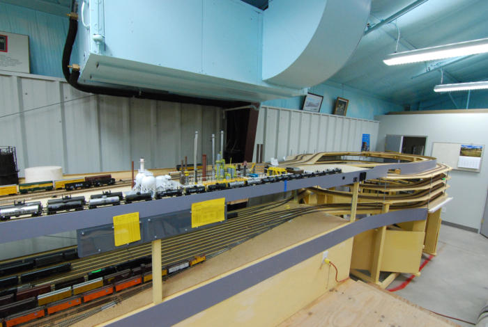
Phase III
When Phase II was fully tested, Phase III, the rest of the layout
was started. It is shown completed in Figure 8 with the main helix
in its final location. The Cheyenne steam yard is at the far end
extending across the back of the picture, and along the right edge
of the picture is the Cheyenne Classification Yard with the staging
beneath it. The temporary location of the main helix for Phase II
was at the extreme end of the far left bench in the photo. The
main helix in its final location now is in the foreground. The small
temporary Rawlins depot is just this side of the Rawlins coal
tower on the left upper bench. The east end of the large Green
River, Wyoming yard is on the lower level visible through the
framing of the main helix, and Rock Springs, Wyoming is on the
lower level on both sides of the aisle extending straight out from
the camera. The track on the upper level bench in the center is
open prairie, the Red Desert area, and on the far end is a siding
and spur off it that is Wamsutter, Wyoming. It is on the east end
of a 3 track, center siding (a Harriman Siding).
Figure 8. Phase III Complete Helix in final location, benches, track work, and DCC done.
THE BUILDINGS THAT HOUSEs THE LAYOUT
The layout is in a 50 x 75 foot layout building beside a separate 30 x 36 foot shop. The building is 50 x 75 feet outside
dimensions with a 4 in 12 pitched roof above walls that are 12 feet high at the edge of the roof. Inside the building is a 75 foot
long by 7 foot wide viewing mezzanine set on a pair of support beams at each end and suspended in the middle from two
oversized girders spaced 25 feet from the each end, and those girders span the 50 foot width of the building. There are no
posts inside the entire interior of the building except for the lower ends of these 2 very large I beams which are about 18 inches
wide at shoulder height at 25 and 50 feet along the 75 foot sides. The headroom under the mezzanine is 8 feet, except on top
of the mezzanine there is 6’ 7” of headroom from the 17” riser to the bottom of the mezzanine. Every other aisle has that 17
inch wooden riser. There are dual 36 inch wide doors at the front and at the rear of the building.
Since Arizona is so hot, geothermal heating and cooling was installed in the building. Instead of air fan condensing coils outside
to convert the gaseous Freon back into a liquid in the heat pump cycle, the geothermal system pumps the gas down into pipes
buried in 10 outdoor wells under the parking lot. Each is about 180 feet deep, and the ground at a constant 72 degree F
temperature below about 10 feet depth is the heat sink that makes the phase change back to a liquid very efficient compared to
blowing 105 degree F air across coils. There are two heat pumps hung from those giant beams that support the mezzanine.
The humidity in the layout building is as dry as just about any part of Arizona, so a dehumidifier is not needed.
There is parking on an asphalt lot, and fire sprinklers in both buildings, an approved water well and a septic tank system with
adequate grading and fill for the septic drain field. There is also street parking and a large retention pond on the low southwest
corner of the lot for water runoff.
The 30 x 36 foot shop building is separate to keep dust from the layout in its own building. In it is a 10” radial arm saw, a 9”
table saw with a 4 x 8 foot top for plywood, a portable table saw, cut off saws for wood and for steel, two drill presses, a 3”
modelers’ table saw, a belt sander, a band saw, and other tools, and storage. It has double 36” personnel doors like the main
building, and a 16 foot wide roll up door to handle large items and my pickup truck. The shop has a swamp cooler that keeps it
cool if you have to work out there, but it does get very humid if run a few hours.
CREW LOUNGE
In May, 2015 an addition to the shop was started to form a 20 x 30 foot crew lounge for crew meetings, lunch breaks, and
lectures. It has a coffee pot, refrigerator, and tables to eat and write on during slide show presentations. It will also house the
collection of books and photographs of Union Pacific history.
LAYOUT CONSTRUCTION DETAILS
The buildings were completed in November of 2011, and three of
us immediately laid out the pattern of benches on the concrete
floor shown in the previous photo. The aisles are all 41 inches
wide, and the spaces between the wider lines are for a
standalone mushroom design of benches. Each of the 3 phases
of bench construction involved a new section of benches on
which we build spline with cork roadbed after sealing all exposed
wood with a light gold prairie dry grass tinted sealer. We then
wired the track for NCE DCC radio operations, and we tested the
track and wiring before we continued bench building.
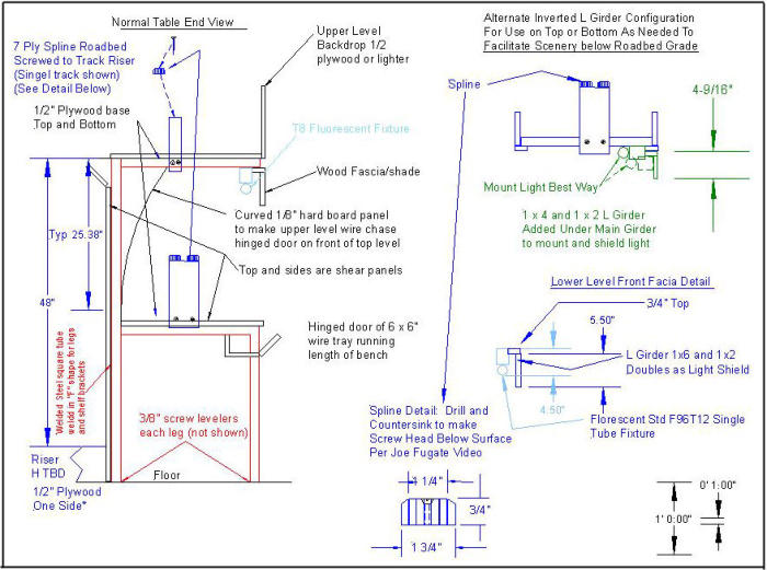
The benches are very sturdy and have steel frameworks made
from 1½” square steel tubing welded to form uprights to hold a
flat surface for each of the two mushroom levels. The next photo
in Figure 9 shows a typical bench end on,
Figure 9. End view of benches in construction.
and this happens to be the two new benches of Phase II, which
were not yet joined by an end cap.
The square tube steel legs are in an “F” shape with a second leg
from the lower horizontal piece for the lower deck down to the
floor. This can be seen clearly in the design drawing of Figure
10. The steel has been painted with the same light yellow sealer
that is used to seal the wood, but the open end of one of the 1½”
square tubes can be seen on the left hand member. Of the two
benches under construction in the foreground, the aisle between
them will eventually have a riser for operators to stand on to
reach the top level on either side of the aisle. The other two
aisles, to the far right and far left will have no risers, so the lower
level benches are worked from the concrete floor. This is the
standalone mushroom design. Eventually, both the riser and the
concrete aisles will be carpeted.
Figure 10. Design of the “F” framed benches
The backs of these two incomplete benches in the photo will have a sheet of ½” plywood screwed to it on the long leg of the “F”
with self-tapping screws. Those sheets are not on these benches yet. This full 4 x 8foot vertical sheet of plywood forms a shear
panel to keep the leg pairs from tilting together from a rectangular to a parallelogram shape. The top sheet of ½” plywood
serves the same anti-shear purpose in the horizontal plane.
Track is not laid on the flat plywood surfaces except for yards. Spline roadbed with cork on it is blocked up to the proper
elevation to model the prototype grades. If a yard is at an elevated level above the bench top we use a separate sheet of
plywood for it. The top plywood sheet of the bench is there for structural strength, and it also keeps an expensive locomotive
from crashing all the way to the concrete floor should disaster strike.
This a “standalone mushroom” design, because there are no benches attached to or supported by walls. This has four
disadvantages and two very big advantages. First, not using the walls to support benches puts a premium on bench stability,
hence the ½” plywood sides for shear panels like on a two story house wall. The top of each bench is also a sheet of ½”
plywood screwed to the steel, and it is a shear panel as well. Together the two sheets of plywood keep the legs from twisting in
any direction. The track elevation is controlled by blocking the spline roadbed up to the desired height above the bench, and the
total block height is adjusted by screws through two blocks, so the blocks do not have to be cut to an exact length.
The second disadvantage to a mushroom design is that it takes a lot more floor space than if benches were attached to walls.
There are benches even up against the walls in most non-mushroom designs.
The two chief advantages to the mushroom design is that with a mushroom design, every other aisle is for operations only on
the upper level and the alternate aisles are used exclusively for the lower level. This means that with appropriate backdrops,
which do not have to be overly tall, operators on different levels cannot see each other. Indeed, each can see only forward or
back on his own track, not onto another level, so the effect is like being out in the country where the tracks before you and those
left or right are all that are visible. The second advantage is even more important. Since all operators in any aisle are working
the same level, there is little possibility of interference between them, and there is no need to stagger upper level and lower
level yards. I believe that these two mushroom advantages, if you have the room for it, outweigh the first two disadvantages
and also the next two.
The third disadvantage is that the extra lumber required to build the riser is not a trivial expense either in time or money. And I
have yet to see a discussion of the end of the riser in any book on mushrooms. There has to be a way up to the riser, be it
steps or a ramp. Either takes a lot of lateral room, so an operator has a chance to see steps or the ramp ahead of him, so he
can account for it as he walks so as not to stumble. This extra space requirement may be hard to accommodate except for a
very large layout.
Finally, a mushroom requires a very high ceiling. The Wyoming division uses 17” risers, so that inside a standard 8 foot ceiling,
which is usually about 94,” the head room is only about 69.” In
my case I tried to get away with 10 foot outside walls in my
design, and then 11, but had to settle on 12 foot walls to get a
reasonable balance of head room under and over the
mezzanine. The extra building height played out as extra
expense in the heavier steel to meet wind shear code
requirements.
OTHER BENCH FEATURES AND DCC WIRING
The photo in Figure 11 below shows completed bench at the far
left with spline and cork and track in place, and there is also a
long thin door open on the lower level fascia. This is a wire
chase that runs all around the layout for most of the DCC
protection circuit breakers. The chases generally have a 5 ½”
square cross section. Not all the wiring goes in the chases, but
we try to put anything that would
Figure 11. Wire chase with hinged door at front of lower level bench. F steel legs also seen.
need access, even wiring, and in particular it is used for all of the DCC block occasional access, in a chase where it is out of
sight, but on the bench front to be easily accessible. This includes DCC circuit breakers and bus bars in pairs (in lieu of terminal
strips) to connect power districts to the wiring mains. The 10 AWG DCC main power buses and the 18 AWG feeders up to the
tracks (and where used any 14 AWG sub power buses) are
generally not in the chases, but we solder all connections, so with
good soldering techniques they are fool proof, so accessibility is
not important.
I do not solder the 18 AWG feeders to the track rails. I spot weld
them with a jewelers’ spot welder, so heating of plastic ties is
impossible and no solder blobs are seen. The spot welds of the
copper wire to the nickel silver rails are very strong and reliable
and the weld bead is small.
Wire chases are built into the upper level also, and this is shown
in the Figure 11. There the backdrop of the lower level is curved
out to near the center of the underside of the upper level bench.
Doors on the far side, the back of the lower level but the front of
the upper level, open just below the upper level bench for the
wire chase.
Figure 12. Lower level bench details for wire chase at Echo, Utah. Also seen are one of the 4 very large steel posts that
support the roof and from which the mezzanine hangs.
The curved backdrop here at Echo, Utah forms the back of the inside of the wire chase. The door behind the curved backdrop
is open and can be seen hanging on its hinges behind the curve. Both the upper level wire chase (behind the curved backdrop)
and the lower level wire chase under the front of the lower level bench all have doors from which many critical non-soldered
items are attached on the insides, out of the way but easily accessible.
Instead of terminal strips, brass bus bars imported from China are used in pairs and are also usually mounted inside the wire
chases or occasionally on the bottom of the upper level bench. The bus bars used are a heavy brass bar with 8 large tapped
holes with screws down into wire holes sufficient for a #10 AWG wire, and the brass is mounted on a pair of nylon standoffs. I
use the bus bars in pairs to make a terminal strip. Terminal strips are commonly used for DCC to separate wiring between
power districts and between breaker districts to facilitate disconnecting a given section of the layout from the rest to isolate
shorts. The bus bars in pairs are simpler, because no jumpers are required as for terminal strips, and they are much cheaper.
The Wyoming Division imported 4,000 of them from China, and most of the leftovers are now available from a Phoenix Hobby
Shop that supplies all of our model railroad equipment and supplies, “An Affair With Trains,” https://www.aawtrains.com/
Also just visible in many photos are some of the 24” single T8 florescent tube fixtures placed on the underside of the top level
benches to light the lower level. The fixtures are placed end to end, and with the average lower level “shelf height” of about 18
inches, the lighting is bright and uniform.
The Wyoming Division imported 1,000 24” long T8 florescent
fixtures and 4,000 each of the 8 screw bus bars at a small
fraction of the unit cost from local big box stores, which import
them from China just like we did. They are steel with a built in
terminal strip for wiring and are less expensive than Home Depot
or WalMart at https://www.aawtrains.com/
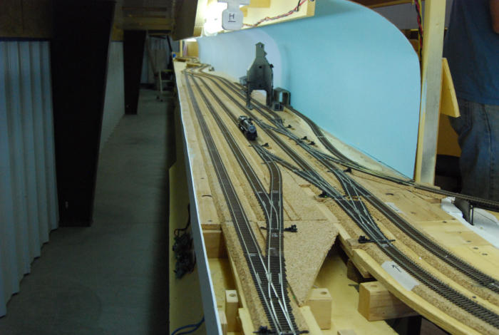
HELICES
The layout has two helices that connect the two ends of the two
levels of benches. The smaller is to connect the ends of the
layout (Cheyenne and Ogden) to the staging. East Cheyenne is
shown with the Frontier Refinery on the upper level at the staging
helix that connects to staging on the lower level as seen in Figure
13. The other end of staging, not shown, connects to the west
end of Ogden, so the point to point layout is made into a circle
with the staging serving both ends of the layout.
Figure 13. Staging helix connecting east Cheyenne on the upper level to staging on the lower level. Frontier oil is on
the upper level.
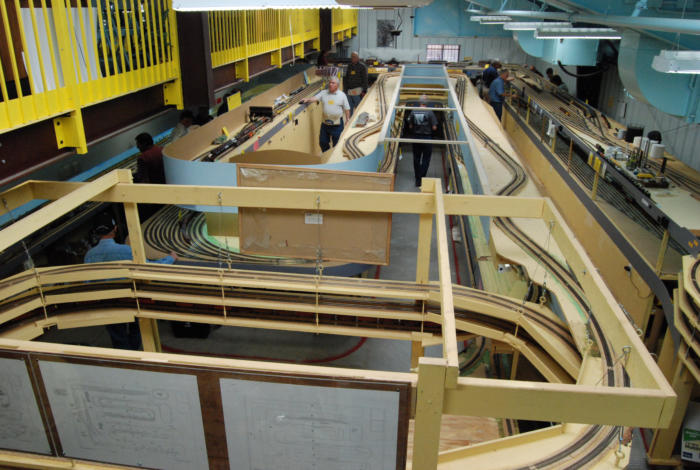
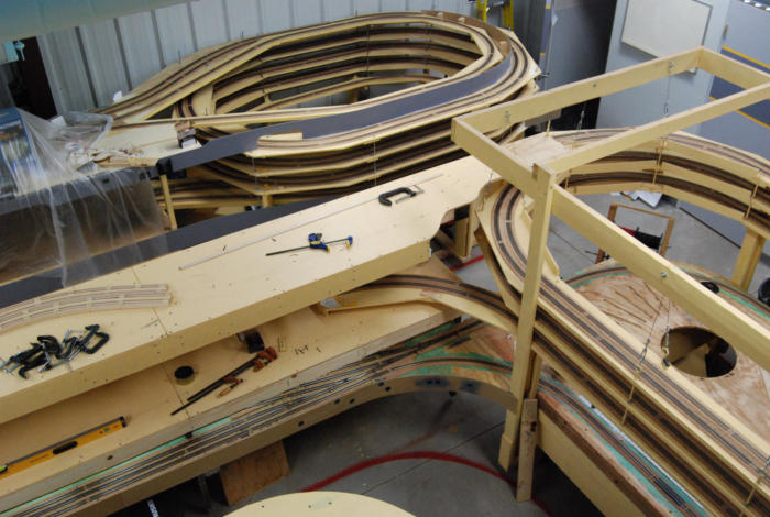
The main helix is shown with the smaller staging helix in the next
photo. It connects the upper and lower benches together in the
middle of the layout, about one half of the way from Cheyenne to
Ogden on the layout. When this photo was taken the upper level
had not been connected to the helix tracks, but the next level, the
lower level had.
A third level can be seen. Technically this third level is hidden
track from a junction at the elevation of the lower bench tracks
about 3 benches away from this view. From that junction that
hidden track drops in elevation under the lower level to end in the
auxiliary staging yard just visible in the photo. This yard is
“Portland, Oregon,” and the hidden track is the Oregon Short
Line (OSL) that leaves the UP main at Granger, Wyoming.
Figure 14. Across the aisle from the Staging Helix is the Main Helix. Each helix connects ½ of the upper level of the
benches to ½ of the lower level.
The Staging Helix has 3 ¾ turns of double track on a minimum 36 inch radius, and is oval in shape with 36 inch straight sides.
The maximum grade is 1.45%. There are also two turning loops on it, one for each bench level to turn passenger trains in
staging so that for their next run they are pointing in the opposite direction than when they left the layout to the loop. An east
bound train through Cheyenne to “Chicago” traverses the loop and returns with its locos pointed west. The upper loop can be
seen as the inner turn of three tracks. The lower level loop is the outer loop of three, and it does the same function for west
bound trains through Ogden to “LA” or the “Oakland.”
The double track Main Helix is similar with 2 ¾ turns, a minimum 36 inch radius, and is oval in shape but with 84 inch straight
sides which gives a maximum grade of 1.68%. Together with the Staging Helix the Main Helix connected to each end of the two
layout levels make a continuous loop, although we always run point to point.
To save plywood the roadbed shelves were cut from 11 inch wide strips of ½” plywood and reinforced with wood cleats or steel
angle. The sections were glued with reinforcing blocks glued and
screwed between the edges of each pair. Sections of assemblies
of each turn were attached together with all 3/8” all thread rod
bought in 8 foot lengths in the electrical department of Home
Depot (more expensive/foot and wasteful 36 inch lengths are in
the rod material boxes in the hardware HD departments). The
threaded rods allow easy, if tedious vertical movement of each
section of helix turn to make a smooth roadbed. Each time we
rolled the helix to a new location, we adjusted it to eliminate
bumps in the sections.
THE REST OF THE LAYOUT
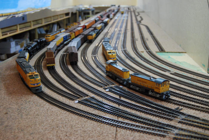
The next photo shows the east end of the large Green River,
Wyoming yard on the lower level (through the Helix
superstructure. In Figure 15, the turntable, roundhouse, and the
Green River will be at the far end of the right hand bench.
Figure 15. The other half of the layout from the mezzanine.
Figure 16. The rest of Green River yard looking west.
Green River is one of the 4 major yards on the layout (including Cheyenne, Laramie, and Ogden/staging). Here engine
changes are made for most trains, and helpers are cut off for east bound trains having completed the climb up the Wasatch
Mountains from Ogden. Blocks are also switched on west bound trains for either California (we call those destinations LA or
Oakland) or Portland up the OSL which junctions off the main at Granger just out of the photo on the next bench left (31 miles
on the prototype).
From Granger the mains go into the very long Aspen and Altamont tunnels, over a train length on the layout and 5,941 and
6,706 feet long respectively on the UP, and they come out into Evanston, Wyoming and from there into Utah. A few miles inside
Utah at a place named Curvo are tunnels 5 and 6 on both the prototype and the layout. These are tunnels bored years apart
and very near each other but at different elevations. Just to the west of the tunnels the west bound main crosses over the east
bound main on a steel overpass. From there into Ogden the layout, always following prototype practice, runs on the left hand
track to take advantage of the newer, gentler grade from Ogden to the Wasatch summit between Curvo and Evanston
(Wasatch, Utah).
The tracks continue with left hand running through Echo out of Echo Canyon and make a 90 degree turn 9on the prototype) to
continue down the Weber River Canyon into Ogden. This sharp right turn is approximated by using the end cap of two benches,
so the model tracks turn 180 degrees.
From echo, which is the location of the Park City Branch junction, the tracks good down grade into Ogden crossing the Weber
river several times. The Wyoming Division models all 10 UP tunnels and all Weber River crossings.
From Ogden the mains go into staging.
Layout Article Page 1 of 2. Click to read.
Layout Article Page 1 of 2. Click to read.


New Video for Wyoming Division Layout
(In three parts)
Videographer Ken Meade and Allen Montgomery made this video
in 3 parts. It follows two freight trains, one eastbound and one
westbound. It covers most of the layout, and especially the upper
level where the scenery and structures are nearing completion.
The track plans of the upper and lower levels are shown
periodically to mark the areas videoed.